 The Society of Robotics and Automation is a society for VJTI students. As the name suggests, we deal with Robotics, Machine Vision and Automation
Making Micromouse from scratch
layout: post title: Making Micromouse from scratch tags:
- Electronics
- Firmware
- Control systems
- Mechanics
- Embedded C
description: Designing a micromouse PCB from scratch and implement maze floodfill algorithm on it!
Mentees:
->Vishal Mutha ->Ojas Patil ->Varun Nigudkar
Building a Micromouse: Journey Through the Schematic and Testing Phase
The Micromouse project is an exciting venture for robotics enthusiasts and engineers alike. The goal is simple yet challenging: to design and build a small autonomous robot capable of navigating a maze with implementation of floodfill algorithm as quickly as possible. In this blog, we’ll take you through the initial phases of our Micromouse project, from the conception of the idea to the schematic design and testing phase. Let’s dive in!
Conceptualizing the Micromouse
Before we began our journey into the world of Micromouse, we needed a solid plan. Our project was divided into several key stages:
- Research and Planning: Understanding the requirements and constraints of a Micromouse competition.
- Component Selection: Choosing the right microcontroller, sensors, motors, and other essential components.
- Schematic Design: Creating a detailed schematic to ensure all components work together seamlessly.
- Assembly and Testing: Putting everything together and testing each part of the system.
Our goal for this blog is to cover the above mentioned stages, culminating in the testing of our schematic design.
Research, Planning and Components selection
The first step in our Micromouse journey was thorough research. We explored existing Micromouse designs, competition rules, and the latest advancements in sensor technology and motor control. Key considerations included:
- Microcontroller: We decided to use the ESP32-WROOM-32E due to its powerful processing capabilities, built-in Wi-Fi, and Bluetooth functionalities.
- Motors: We chose the TT Motor – N12 2.4V 1200RPM Metal Gear Motor With Encoder for precise movement and control.
- Sensors: Infrared (IR) sensors were selected for obstacle detection and maze navigation.
- Motor Driver: The DRV8833 motor driver was selected for controlling the motors efficiently.
- Power Supply: A 3.7V battery with capacity of 1500mAh chosen to power the ESP32 and other components.
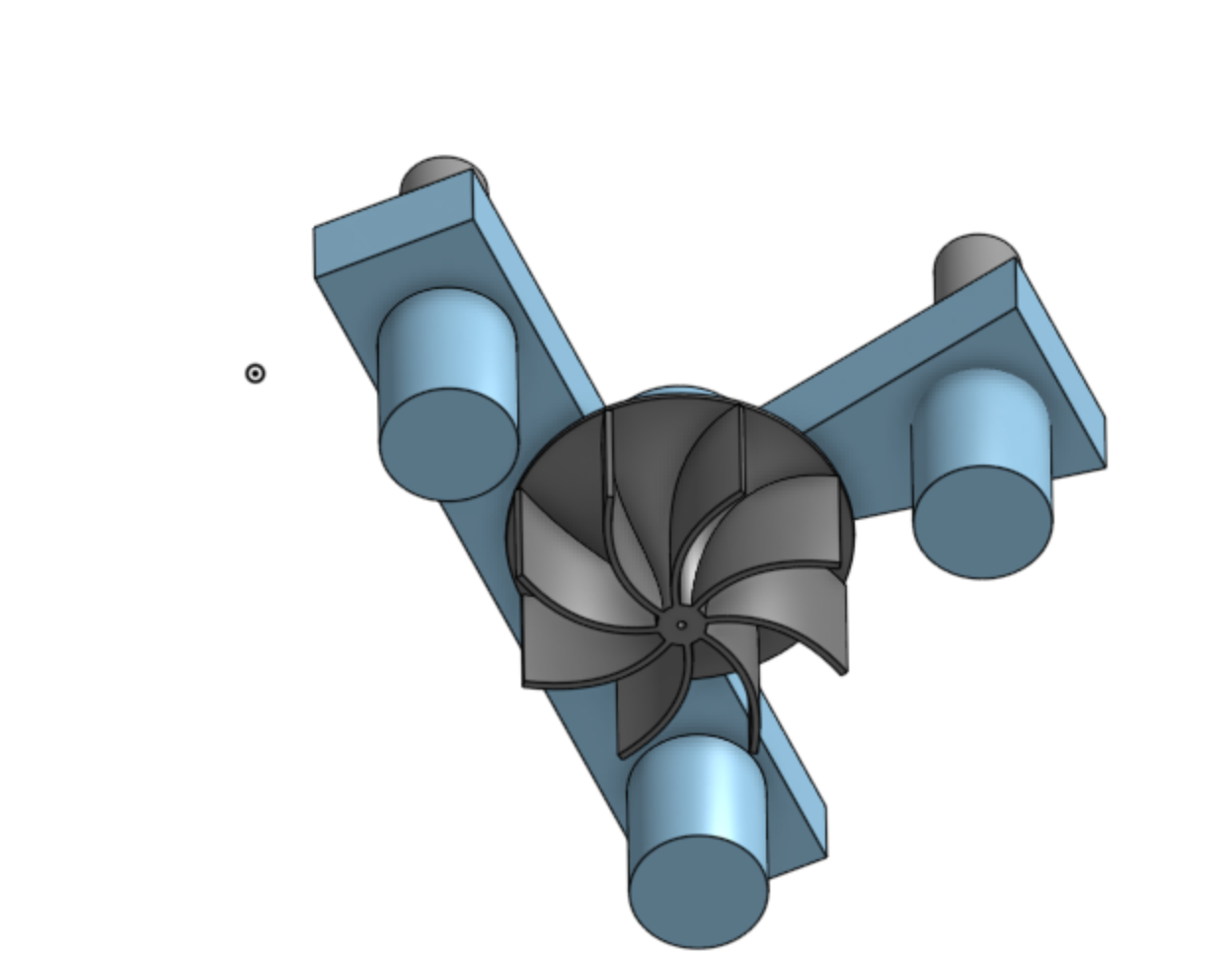
- Suction Fan: A cad model of suction fan is designed with it’s coreless motor 8520.
- i/o Expander PCA9536D: This IC gives extra GPIO pins.
Schematic Design
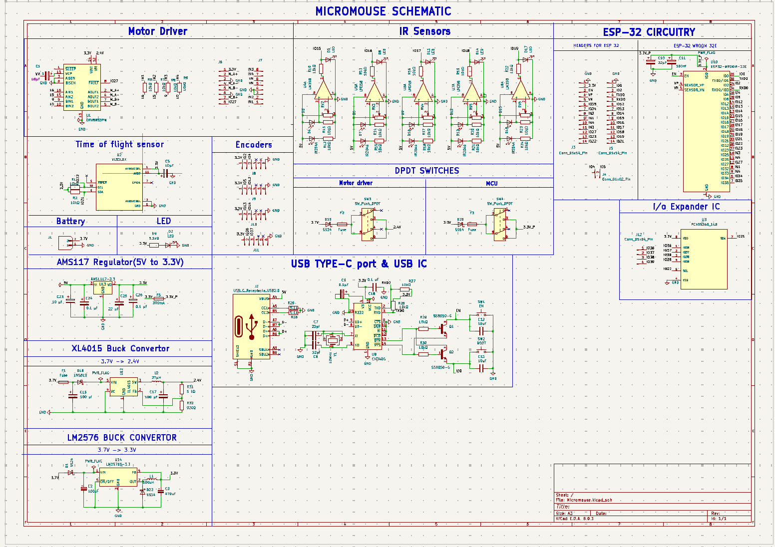
Creating the schematic was a crucial step in ensuring that all components would work together harmoniously. We used Kicad for designing our schematic. The design included:
- Microcontroller Connections: Connecting the ESP32 to the motor driver, IR sensors, and power supply.
- Motor Driver Circuitry: Ensuring proper connections between the DRV8833 and the motors.
- Sensor Integration: Placing the IR sensors at strategic locations for optimal maze navigation.
- Power Regulation: Incorporating LM2596, XL4015 and AMS117 voltage regulators to maintain stable power supply to the ESP32 and motors.
Here’s a simplified version of our schematic:
Testing the Schematic
With the schematic in hand, it was time to test our design. This phase involved: 1.Firmware code writing: For testing any component we wrote code for firmware which in this case is espidf.
- Breadboard Prototyping: Assembling the circuit on a breadboard to test individual components.
- Component Testing: Verifying the functionality of each component such as motors, motor driver, and sensors.
- Power Testing: Ensuring the voltage regulators provided stable power to the circuit.
Challenges and Learnings:
- Power Issues: Initial power tests revealed instability, which was resolved by fine-tuning the voltage regulators.
- Sensor Calibration: The IR sensors required precise calibration to accurately detect obstacles.
- GPIO pins shortage: While making the connections for schematic with all the components, faced a issue when we tried to connect four encoders of four correspnding motors, each needed four GPIO pins so to resolve it we used and i/o Expander IC. It gave us four extra pins and our encoders were successfully integerated in the ciruit.
Future plans and challenges
- We are about to our work on pcb layout and designing. The difficult part of layout is routing.
- Once the hardware is completed we will be working on implementation of floodfill algorithm and setting up the PID of the bot.
Conclusion
Reaching the schematic and testing phase of our Micromouse project has been an enlightening experience. We encountered challenges that pushed us to think creatively and refine our design. Our next steps involve designing the PCB, fabricating it, and moving on to the assembly and further testing phases.
Stay tuned as we continue our journey, sharing insights and experiences from the exciting world of Micromouse building. Whether you’re a novice or a seasoned engineer, there’s always something new to learn and explore in robotics. Happy building!
For any further updates you can check our repositary.