 The Society of Robotics and Automation is a society for VJTI students. As the name suggests, we deal with Robotics, Machine Vision and Automation
Building a Video Card on FPGA!
Mentees:
What is this project about?
The main aim of this project is to build a video card capable of displaying images on a monitor. The video card will send analog signals to a monitor using an interface called Visual Graphics Array (VGA). The video card will be synthesized on a FPGA board. The project requires fundamental knowledge of FPGA boards, CRT monitors’ workings, and electronic logic gates.
What are FPGAs?
Field-Programmable Gate Arrays (FPGAs) are semiconductor devices that can be electronically reprogrammed to perform almost any function you want, unlike regular microprocessors, which run software instructions on fixed hardware architecture. This means you can design your own digital logic on an FPGA.
So, why FPGAs?
Building a video card is a complex task that involves handling data quickly and efficiently to display images on a screen. Field-Programmable Gate Arrays (FPGAs) are a powerful choice for projects like building a video card because they offer a unique blend of flexibility, performance, and customization that traditional processors simply can’t match. FPGAs can handle multiple operations simultaneously as well, making them ideal for tasks that require processing large amounts of data quickly, like rendering graphics or video streams.
Starting with FPGA programming
In the beginning of this project, we learned about hardware descriptive languages that are used to program FPGAs. There are two widely used HDLs, namely VHDL and Verilog. VHDL is the older language and follows a more complex structure. Whereas Verilog is comparatively newer, more concise, and very similar to C, In this project, we are using Verilog. So, to get started with Verilog, we started learning it by reading tutorials on ChipVerify and solving Verilog problems from the HDLBits website. These problems started with programming simple logic gates and modules and getting to know the basis of the Verilog programming language. This was followed by intermediate problems based on multiplexers and sequential circuits such as D-flip-flops and finite state machines (FSMs).By completing the course, we learned how verilog syntax and Finite State Machines work. The previous problem-solving skills developed quickly due to prior knowledge and experience of other programming languages like C/C++, Java, and Python.
How VGA works
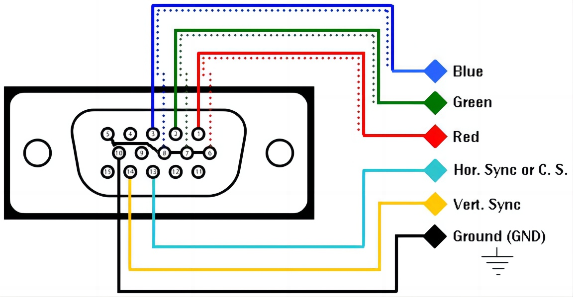
VGA stands for Visual Graphics Array, and it is an interface to send information about the image from a computer’s video card to the monitor. VGA connectors are typically blue and have 15 pins arranged in three rows. This connector transmits the video signals from the computer to the monitor. Most of the pins used in the VGA are ground pins, but the pins we are most concerned with are the RGB pins (3 separate pins for red, green, and blue colors), as well as the horizontal and vertical sync pins. The RGB pins carry analog signals that provide information for the intensity of the red, green, and blue components of the image. By varying the voltage of each signal, different colors can be produced.The H_sync and V_sync signals synchronize the timing of the image data. H_sync signals the end of a line and the start of a new one, while V_sync signals the end of a frame and the beginning of a new one.
Pixel rendering using VGA
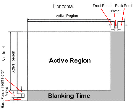
The rendering of pixels will be controlled by the H_sync and V_sync signals coming from the VGA.Both of these signals can be divided into four specific interval timings: the visible area, the front porch, the sync pulse, and the back porch.
-The visible area is the period during which the actual image data is displayed on the screen. It is the active portion where pixels are lit up to form the picture. -The front porch is a short interval after the visible area and before the sync pulse.
-The sync pulse is the part of the signal that resets the position of the display system to the start of the next line (horizontal sync) or frame (vertical sync). It is essential for keeping the display in sync with the input signal.
-Last but not least is the back porch, which follows the sync pulse and precedes the next visible area. It allows time for the display system to stabilize before drawing the next line or frame. We have decided to use 800 * 600 VGA signals with a 50 MHz pixel frequency and a 72 Hz refresh rate in our project. We have been able to output the above interval timings correctly on a digital signal oscilloscope using the Arty A7 35T FPGA development board.
Current Progress
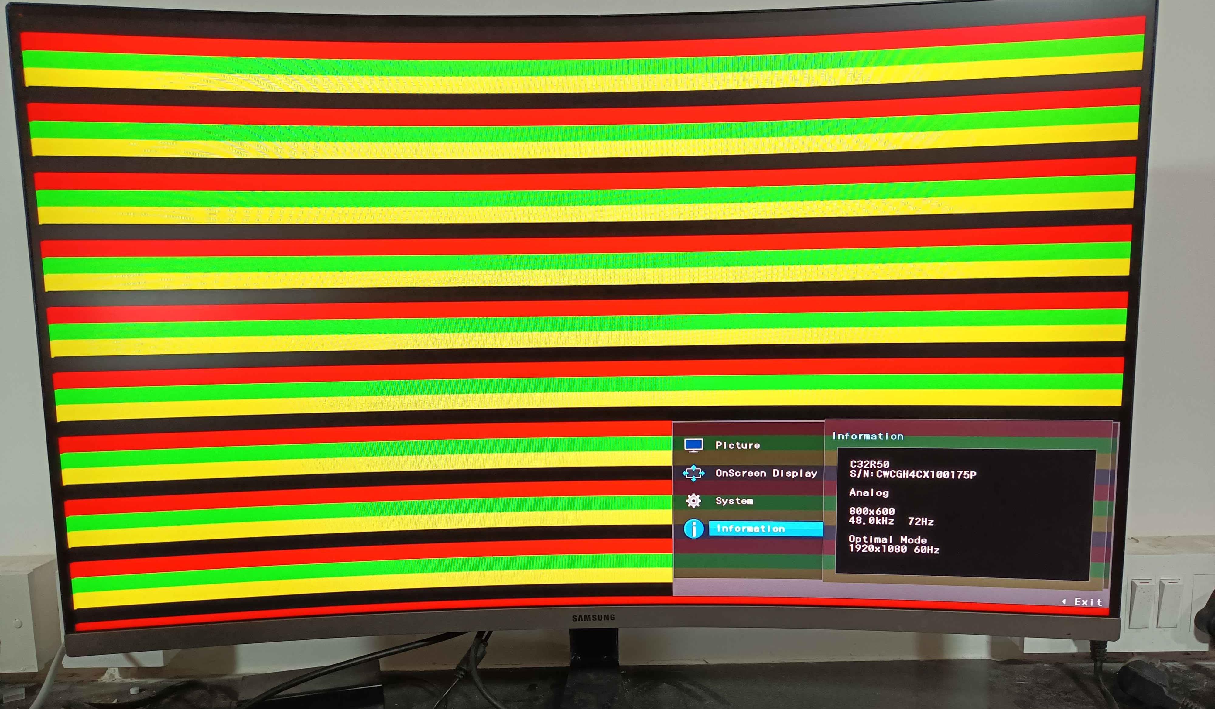
We have completed writing H_sync and V_sync signal scripts as well as tested their timings and waveforms on an oscilloscope.Also, we have successfully tested if the monitor is rendering pixels via a VGA connector connected to the FPGA by simply displaying lines of RGB colors.
 We are currently working on adjusting the intensity of RGB signals using resistors and writing the code for the same.
Problems we faced
The initial problems involved the understanding of finite state machines and how their working varied from simple logical statements, due to the hardware implications varying from the software results or our thinking process. Testing the timings of the sync pulses was also a significant problem due to improper readings appearing on the oscilloscope due to the presence of jumper wires, which are sometimes unreliable.