 The Society of Robotics and Automation is a society for VJTI students. As the name suggests, we deal with Robotics, Machine Vision and Automation
Phase Control Rectifiers Explained in 2 Minutes
Some years back AC to DC power alteration was attained using mercury arc rectifiers and motor generator sets. The common, normal diode rectifiers were not used because neither are they are able to handle high power, nor do they give us control over the output voltage. The modern AC to DC power converters are intended to handle high current and high power. So, the trend has shifted to using thyristors in place of diode rectifiers. Presently, most of the AC to DC power converters are thyristor-ized with the help of Phase Control Rectifiers.
The term PCR or Phase controlled rectifier is one type of a rectifier circuit in which the diodes are replaced by Thyristors or SCRs (Silicon Controlled Rectifiers). Unlike a diode, a thyristor is a gate-control electronic switch which can be turn on by gate pulse and can be turn off when thyristor is reverse-biased. Hence, output of a PCR can be control by controlling firing pulse (gate pulse).
Now then, lets get to how it works. Most of us may not be aware of what a thyristor is. We can consider a thyristor to be a switch and, for simplicity, believe that it can be turn on and off like normal one. Now you have some switches which you can control. To extract the DC from the AC you have to wisely turn some switches on and some off for a particular period of time.
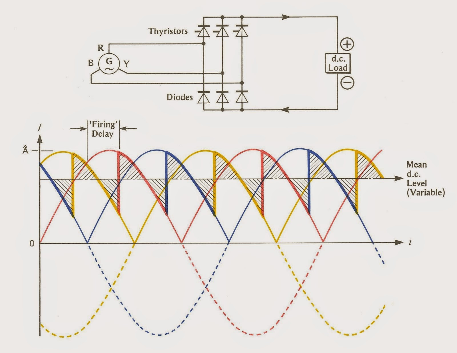
Taking the example of the three phase PCR which shown in the diagram at the start of this post, we can see three thyristors (the one with the symbol like diode with a dash) in series with each phase wire . Now when the phase Y is positive and its voltage is greater than the other two phases we turn on the thyristor in series with the phase Y and turn off the others, causing current to start flowing from upwards to downwards through the DC load. After some time, when phase R is positive and its voltage is greater than other two, we turn on the thyristor which is in series with phase R and turn the others off. Current still flows from upwards to downwards through the DC load. This process goes on, and the result is : Hence we have extracted DC voltage from AC successfully! (lab journal conclusions :P)
Now, coming to how the output DC voltage is varied. The firing delay, which is the time after which the respective thyristors turn on and off when the phase with the greatest positive voltage changes (as shown in the graph) is made use of here. The firing delay is varied, hence changing the Mean DC Level that is supplied by our circuit.
Advantages of PCR:
- Output voltage can be control using firing pulse delay.
- As thyristors are capable of handling around 100A and 1200 ~ 1500V PCR can be operated over a large range of voltage and current.
Applications of PCR:
- DC motor control in steel mills
- Battery chargers
- High voltage DC transmission
- AC traction control using DC motors
For the inquisitive, who want to find out more about thyristors and PCRs, here’s a few useful links:
So that’s it for today folks, hope you enjoyed learning about PCRs as much as I did..!